1. Problem to be solved or desired purpose of the machine is completely and clearly stated.
2. Possible mechanisms that will provide the desired motion or set of motions are selected.
3. Forces acting on and energy transmitted by each element of the machine are determined.
4. Best suitable material is selected for each of the machine element.
5. Allowable values of stress and deflection are determined for each machine element, depending upon its material and functional requirements.
6. Size and shape of each machine element is determined so that it can withstand the applied loads without failure.
7. Dimensions of the machine elements are modified considering manufacturing aspects.
8. Assembly and detailed drawings of the machine are made with complete specification of materials and manufacturing methods. |
|
|
| |
|
|
|
| Project Introduction :: |
| |
|
|
The invention of the X-Y plotters is to recording or plotting two dimensional data on a rectangular coordinate system. This study emphasizes the fabrication of a XY plotter by using mechanism from scanner and microcontroller system (Arduino) to control the movement of XY axis. Modeling and analysis on X-Y plotter is carried out through the computer linked with the Arduino software.
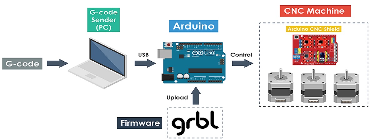
The X-Y plotter is designed to recording and plotting two-dimensional data on a rectangular coordinate system. The material selection of the mechanism was made considering the cost and wide range of applications such as servo motor. Servo motor can be differentiated through the cost, peak torque capability, speed range to compromise the standard and application of the system. The dynamics of a dual-drive servo mechanism and develops an XY gantry model consisting of two motors for Y control with another motor sliding the gantry in the X direction. The design uses two parallel rails for Y-motion with a bar spanning across the rails which holds the end effectors of the system. In the other hand, the accuracy of plotting is the main issue to be concerned on the fabrication of X-Y plotter. G-Code is a function to tell the machine to move to various points at the desired speed, control the spindle speed, and turn on and off various coolants . In this X-Y plotter system, G-Code is employed by the part programmer to specifying the coordinates of the point to be moved and giving the normal vector to the surface at that point. For the core system, Arduino system is most familiar and low cost and easily controlled function of the Arduino system contributed on simplifying the building circuit of the microcontroller in the X-Y plotter.
|
|
|
| |
|
|
| Methodology :: |
|
|
| |
|
|
We need to find something to attach the one of the stepper-rails vertically to our construction the Y axis of our CNC machine. Attach it on your surface, in this part you will need some screws and nuts. The X axis is attached to two plastic parts and it was cut it to fit the construction. Ensure to put the Y axis straight to x-y plotter base and the X axis vertically in this (90 degrees). On that surface the servo motor (Z axis) will be attached to the pen base. Pen t must be able to move up and down with the aid of servo motor. Now it will have to attach a hard surface on Y axis. On this, it will put the paper piece to print the texts or images that we programmed The printing area. For steppers motors wiring, it will find a 'testing' code for x and y axis. If the steppers doesn't work properly, the correction can be obtained by working combination by changing the cables between them and the L293D ICs. To make G-Code files that are compatible with this X-Y plotter, the Java Programming is used. |
|
|
| |
|
|
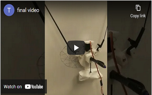
Myself and my group members discussed with our remote instructor Mr. Sibu Saman, who insisted us for making a Vertical Plotter and has given us the basic concept and ideas to make a vertical plotter using arduino and stepper motor. Our group project is a hanging drawing machine (Vertical Plotter) that moves its hand in both X & Y axes . The hand consists of a pen attached to a 3D printed holder which connected to two stepper motors from the right and left sides. The machine should be attached vertically to a board and being controlled by a G-Code.
The aim of this machine is to enable the user to draw anything on a board or a wall. Requirements are simple as the user should just fix the machine on the panel want to draw on and enter the size of the drawing area and machine specifications.
|
|
|
| The required components for making of Vertical Plotter are as follows :: |
|
|
| |
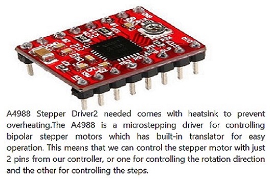
1. Arduino UNO
2. Power adapter
3. Servo motor
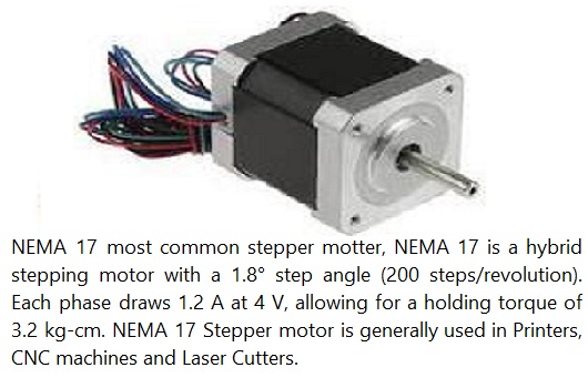
4. Stepper motor
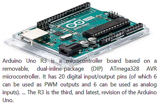
5. CNC shield
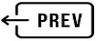
6. Stepper motor driver
7. Heatsink for the stepper motor driver
|
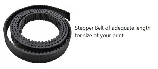
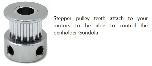
8. Toothed belt
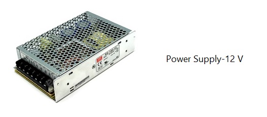
9. Power supply
10. Digital multimeter
11. Screwdriver
12. Wooden frame
13. Pend & paper
14. 3d printed pen holder
15. 3d printed steppter motor holder |
|
|
|
|
|
|
| Description of Components :: |
|
|
| |
|
|
|
|
| |
|
|
|
|
| |
|
|
|
|
| |
|
|
|
|
| |
|
|
|
|
| |
|
|
|
|
| |
 |
|
|
|
| |
|
|
|
| Circuit Connection Diagram |
|
|
| |
 |
|
|
|
|
|
| |
|
|
|
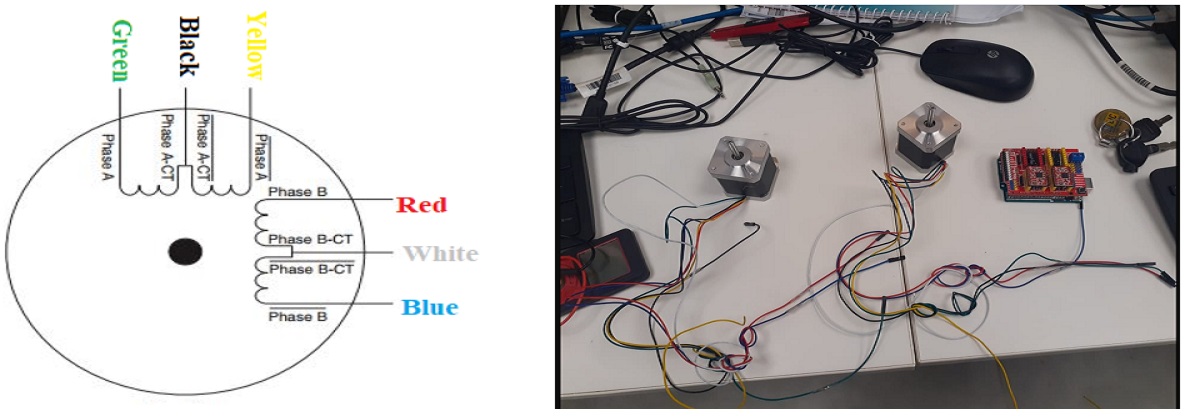
| Finding the 2 pairs out six cables in stepper using multi-meter |
|
|
| |
 |
|
|
| |
|
|
|
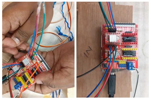
Here is the connection between the stepper and servo as shown in the figure. For Servo -x, +5v and GND from the CNC shield. We used the power supply where we can adjust the current and voltage but 12v to 24 volt we had given 13v and 1Amp. |
|
|
| |
|
|
|
| GRBL Control :: |
|
|
| |
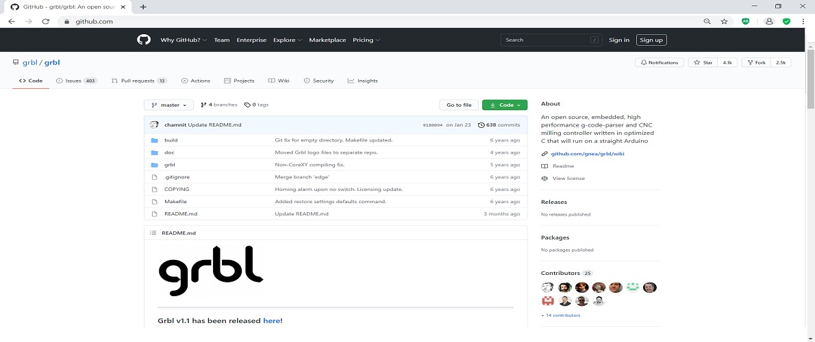
Grbl is a no-compromise, high performance, low cost alternative to parallel-port-based motion control for CNC milling. It will run on a vanilla Arduino (Duemillanove/Uno) as long as it sports an Atmega 328. The controller is written in highly optimized C utilizing every clever feature of the AVR-chips to achieve precise timing and asynchronous operation. It is able to maintain up to 30kHz of stable, jitter free control pulses.
It accepts standards-compliant g-code and has been tested with the output of several CAM tools with no problems. Arcs, circles and helical motion are fully supported, as well as, all other primary g-code commands. Macro functions, variables, and most canned cycles are not supported, but we think GUIs can do a much better job at translating them into straight g-code anyhow.
Grbl includes full acceleration management with look ahead. That means the controller will look up to 18 motions into the future and plan its velocities ahead to deliver smooth acceleration and jerk-free cornering. |
|
|
| |
|
|
|
| |
|
|
|
| |
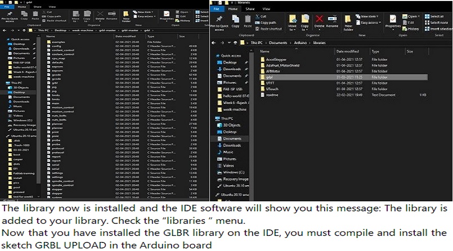
Download GRBL, this is the direct link:
https://github.com/grbl/grbl/archive/master.zip
Extract on the desktop the grbl-master folder, you find it in the file master.zip
Run the Arduino IDE, currently I’m using version 1.8.1
From the application bar menu, choose: Sketch -> #include Library -> Add Library from file.ZIP…
Select the folder grbl that you can find inside the grlb-master folder and click on Open |
|
|
| |
|
|
|
| To know the Perfect Way for Settings of GRBL |
|
|
| |
These are the steps to be followed to mill a design
1.Make a 2d Drawing of the design you want to make
2.Consider the tolerance
3. Put the drawing into layers as per the cutting scheme
4.Arrange the pieces to minimize the wastage ofthe material
5.Leave ample distance between pieces to avoid overlap |
|
|
| |
|
|
|
|
Settings of GRBL is an important point to start the development. The first point that comes here is the primary set up in the software. So let’s go with the flow step by step. |
|
|
Step-1 |
|
|
|
First of all, go to the software and then go to the file section where one can easily find some tools section. |
|
|
|
Step-2 |
|
|
| |
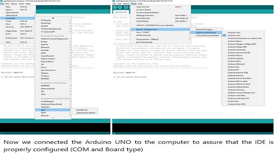
1. Go to the Tools section and select the baud rate according to the hardware. It is a device-specific method.
2. So, try it and see which baud rate gives you the right response at all. Before selecting the baud rate, there is one more thing to select that is an Arduino model.
3. Select Atmega 8 if it is an Uno model or select the nano model by checking the model number written on the device. |
|
|
| |
|
|
|
| Step-3 |
|
|
| |
1. Type ‘$$’.
2. It should give a list then. It will consist of some gradually increasing numbers.
3. Then select them, and it will execute that to set up the device. |
|
|
| |
|
|
|
Approach for proper use of GRBL |
|
|
| |
Now, there is something that is to discuss how to use the GRBL. Well, GRBL is very easy to use.
One who uses GRBL does not necessarily have any knowledge about it previously. Yes, if one has a basic knowledge of coding, then it is good to go.
They need to define value first and then go for the console. There are the settings page and pendant page. The pendant page doesn’t mean at all.
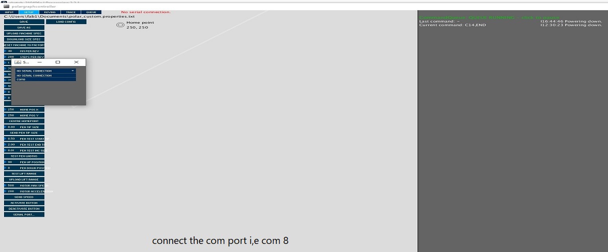
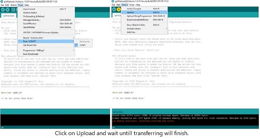
The main configuration is done with settings. Then it needs to connect the USB with PC and the Arduino. Update the connection type by giving specific commands. Then see what response the firmware gives.
If the response is positive, then go with the flow. Otherwise, check the baud rate. Also, check the settings clearly. Check the model number as well. |
|
|
What should one know about |
|
|
| |
1. All the technologies that are evolving today are connected with the same root somewhere. The main brain behind all of those is the specific hardware and the firmware that they use. So, simply GRBL is also a similar firmware which is used in Arduino.
2. Now Arduino is universal hardware that has some collection of ports in-built. One can easily imply any of the projects with any type of circuitry with this. Normally it is used to control stepper motors in a more controlled way.
3. It is very necessary to control the speed of the stepper. With a stepper motor, there are some projects like a laser cutter, automatic pain controlled printer, 3D printer, etc. can be made easily.
So, on this type of innovative project does need GRBL software and G-Code, where the implication of human language to machine language is very easy.
|
|
|
| |
|
|
|
|
|
|
| |
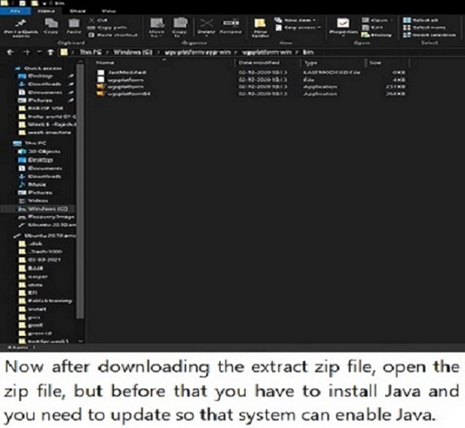
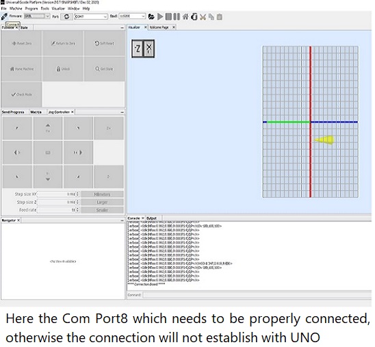
Universal G-Code Sender
A full featured G-Code platform used for interfacing with advanced CNC controllers like GRBL , TinyG, g2core and Smoothieware. Universal G-Code Sender is a self-contained Java application which includes all external dependencies and can be used on most computers running Windows, MacOSX or Linux.
Now you can test your Arduino with GRBL with Universal G-Code Sender, the link of the project on GitHub is https://winder.github.io/ugs_website/
and direct link to the download page is https://winder.github.io/ugs_website/download/
Universal G-Code Sender is a multi-platform program written in Java which requires a version 7 or higher to run.
| |
| |
|
|
|
| |
|
|
| |
|
|
| |
|
|
|
| |
Polargraph |
|
| |
|
|
|
| |
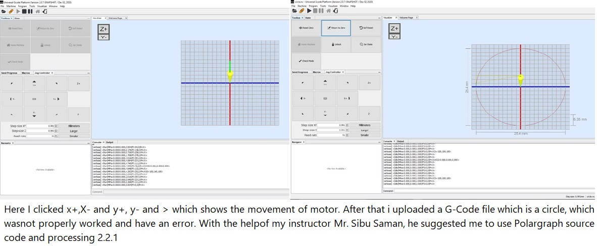
This machine, a variation on the hanging-pen plotter is a conspicuous and wilfully naive attempt to break out of the pristine, pixel perfect, colour-corrected space that exists inside our computers. It's a drawing machine, that takes a pen (a human tool) and uses it to draw in a singularly robotic way, with some grand results.
A polar plotter also known as polargraph is a plotter which uses bipolar coordinates to produce vector drawings using a pen suspended from strings connected to two pulleys at the top of the plotting surface. This gives it two degrees of freedom and allows it to scale to fairly large drawings simply by moving the motors further apart and using longer strings. Some polar plotters will integrate a raising mechanism for the pen which allows lines to be broken while drawing. |
|
| |
All the necessary files can be found in the repository. The Micro-controller firmware and Application can be found inside this zip file. |
|
| |
|
|
|
| |
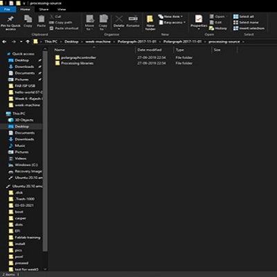 |
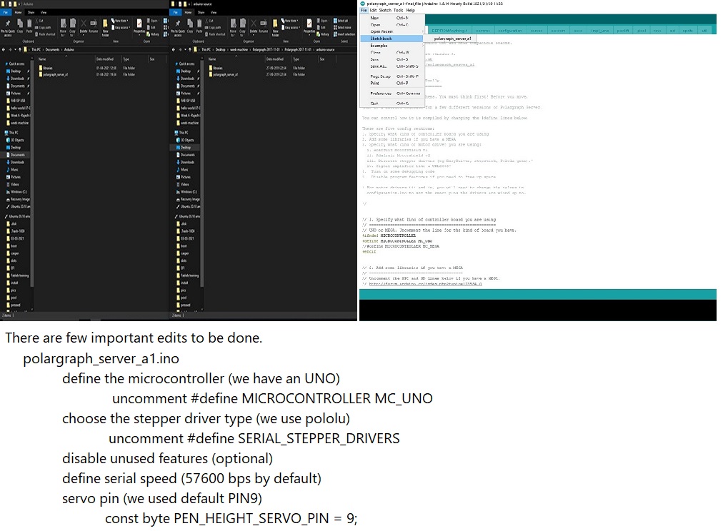
Extract the zip file and copy the polargraph_server_a1 folder into the Arduino .
Copy the libraries to be used for the Arduino source code.(Copy the libraries in the Polargraph libraries folder to the Arduino libraries folder.)
Find the source code to use for the Arduino. (Open the cource code in the Polargraph/ arduino-source/ polargraph_server_a1 folder.)
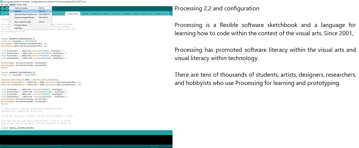
Upload the polargraph_server_a1.ino source code to the Arduino.
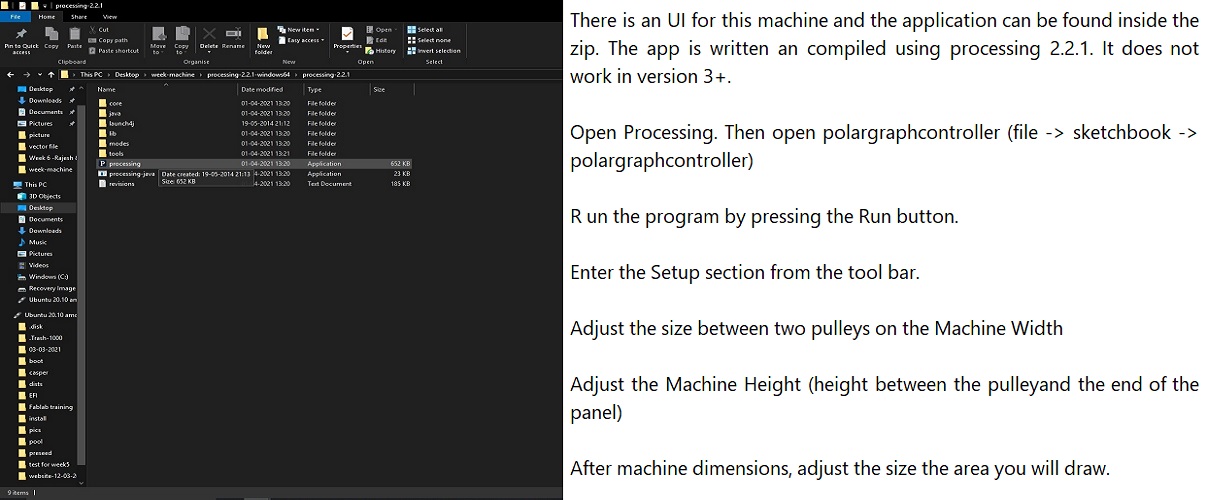
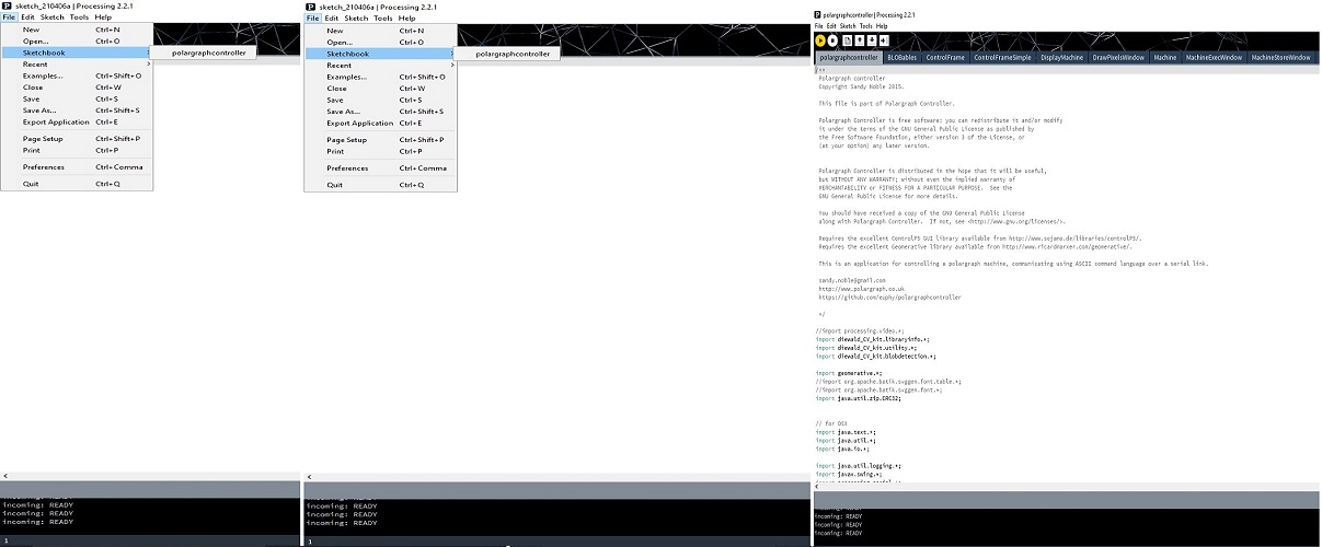
Then open the Processing software. Find the SketchBook folder from file / preferences/ sketchbook/ location
Find the Processing libraries in the Polargraph folder. Copy all the library folders in this folder into the libraries folder in the Processing Sketchbook folder.
Move the Polargrapcontroller folder inside the Polargraph folder/ processing-source/ folder into the sketchbook folder.
|
|
| |
|
|
|
| |
|
|
| |
|
|
|
| |
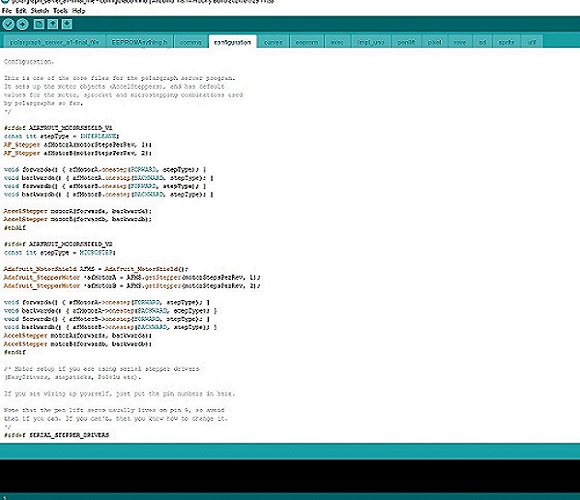 |
configuration.ino
step and direction pins for the controller
#ifdef SERIAL_STEPPER_DRIVERS
#define MOTOR_A_ENABLE_PIN 8
#define MOTOR_A_STEP_PIN 2
#define MOTOR_A_DIR_PIN 5
#define MOTOR_B_ENABLE_PIN 8
#define MOTOR_B_STEP_PIN 3
#define MOTOR_B_DIR_PIN 6
AccelStepper motorA(1,MOTOR_A_STEP_PIN, MOTOR_A_DIR_PIN);
AccelStepper motorB(1,MOTOR_B_STEP_PIN, MOTOR_B_DIR_PIN);
#endif
|
|
| |
|
|
|
| |
 |
|
| |
|
|
|
| |
 |
|
| |
|
|
|
| |
|
|
|
| |
Downloads |
|
|
| |
|
|
|
| |
 |
|
| |
|
|
|
| |
 |
| |
|
|
|
| |
|
|
| |
|
|
|
| |
 |
|
| |
|
|
|
| |
 |
|
| |
|
|
|
| |
 |
|
| |
|
|
|
| |
 |
|
|
| |
|
|
|
| |
|
|
|
| |
|
|
|
| |
 |
|
|
| |
|
|
|

